Sunday, April 20, 2014

Final Project

Initially, I wanted to conflate CATIA product and knowledge patterns to generate massive folding structure like above. Not until the end did I realize that this is impossible. Here is my failure process.

This is the pattern I want to genereate. Seems not that hard at first.

the output folding unit is controlled by the open angle and the size parameters

I imagined the red line would be the inputs within the overall framework. All I need is the framework now.

Then I realize I cannot foresee the overall framework, because the it is bottom-up generated by the units, which is completely a different approach compared to the top-down framework layout as previous projects did. 

"Karl, help me!"
"The best way to do folding structure is assembly mode. Even you figured out the framework, you cannot use either powercopies nor knowledge patterns to instantiate your unit because it is assembly mode."
"What the f!"

All right, I can manually make it.
The folding is controlled by the same open angle parameter of all the units. They seems pretty rigid. 

So I fold a physical model to test the flexibility. Apparently within a folding system, each unit behaves accordingly, but seems they could behave somehow differently.

Can I differentiate each unit in CATIA? Not until the end did I realize that my physical model cheated me. The gif animation shown above is the only process that it can behave. It is completely as rigid as we see. Here is my failure process.

"Help me Karl, I want to differentiate the units!"
"David made it, Look!"

So I grab David to learn flexible-rigid sub assembly command, which made his sub-assembly behaves independently. 
It took me quite a while to know that I have to delete the angle parameters and the frame and leave the sub-assembly with triangular panels only.

The opening is controlled by offset length under the highest assembly now. Then I changed the individual open offset length.

Failure! No matter how minor the change I made to the offset, it always make the constraints inconsistent. Only one unit at the bottom changed a bit.

David and I looked at the screen, then the model, for quite a while. Then he said,
"Triangular shape is rigid. You cannot make any difference to the units' openings unless your units are different."

What a learning after doing!

I guess the further exploring maybe create different units in order to fold in a nonlinear way, like Daniel did shown below. He made it in grasshopper with Rigid Origami Simulator. I hate CATIA!


Sunday, April 6, 2014

Project010 Knowledge Patterns II

 After I changed the color, CATIA suddenly reminds me of a pineapple.Secondly a pangolin. They fit perfect.


The project this week is adding surfaces based on the framework I created last week.The cell looks like a bubbled material.


 Continued thinking that way. The tensile material may not have a sharp corner. So I fillet the corners,with radius driven by the cell size, so the cells may be connected by tensile strings at corners when digital fabrication process is considered.Above are performance of different radius parameters. large radius may cause problem.


The elevation of each bubble is driven by cell size too, additionally controlled by a multiplier. Large multiplier may cause problem.


The overall control of surface, density and performance

Saturday, April 5, 2014

Project009 Knowledge Patterns I


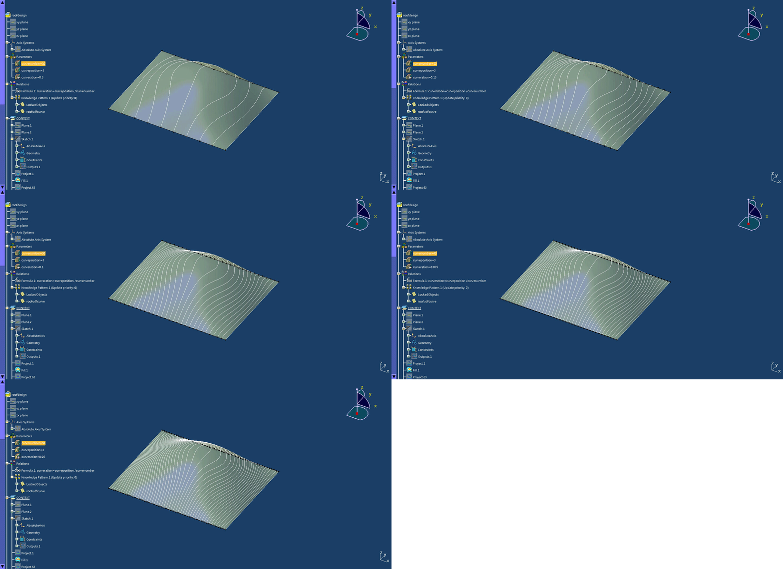
The line connecting same ratio points on the top and bottom edge of the surface is projected onto the surface, producing a framework for future overlay. The number of curves is manually controlled to achieve expected density.


 The surface is controlled by boundary line and the passing point


The top and bottom lines can also be isolated from the surface and be controlled separately, creating a potential muli-sections surface. Therefore, the performing curves can be interpreted as the dialog between the the fill surface and the multi-sections surface.

Project008 Powercopy Knowledgeware


The vertical curve is the only input while making powercopies of those pipes. 

The color of each pipe is controlled by the pipe's surface area. While the global parameters are the factor controlling the multiplicity of the pipe length and the color cutoff area, the local parameters are the random ratio of point on the curve and the random rotation angle range. Consequently, two separate excel sheet is set in order to generate the random numbers, thus they are able to behave independently. 

length factor

random position along the curve

control of random rotation angle range
The problem is that the diameter of the pipe profile and the length of the pipe is supposed to reflect the distance between the projection of the origin point on normal plane and the point on curve, but when I change the curve, the length of the pipe became so exaggerated. A new formula relationship between curve and pipe figure would be productive.

Sunday, March 23, 2014

Project007 Flat Form


Unfold command is especially helpful to manufacture a digital model by unfolding and flattening the 3D form.

2D framework based using affinity command
3D framework by projecting the 2D framework to a bulging surface
build geometry base on a set of 4 points
unfold geometry
powercopies
geometry controlled by affinity factor
geometry controlled by bulging surface 

Saturday, March 15, 2014

Project006 Powerful Replication


Power Copy is especially powerful when dealing with cellular architecture envelope, which requires much labor in replicating units following the same rule.

Instead of picking unit cell grid point one next another (a-a-b-b), my unit grid point is partially intersected (a-b-a-b), in order to produce a sense of weaving.

 One way of the framework control is through the peak height control of the base


Monday, March 10, 2014

Project005 Framework Form

Peace Bridge_Santiago Calatrava


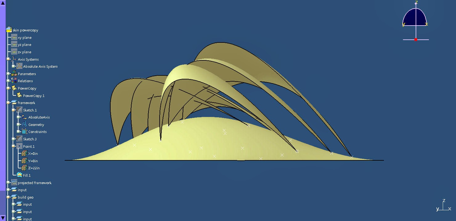
Framework is one of the dominant methods in generating 3D form. More crucially, framework form is highly relative to the aesthetic of building structure and the technique of building construction, which can be radically expressive, like the work of Santiago Calatrava.


Modeling framework form in CATIA enables the optimization of the framework at the technical behavior level by simulating stress distribution in STAAD. The stress analysis via STAAD is coming later.